The APS PAR lattice consists of 2 superperiods, with 2 quadrants per superperiod. The magnets are powered in series by families. There are 8 dipoles (BM) and 16 focusing quadrupoles (QF). Defocusing is provided by the wedge effect of the dipole magnets. The PAR has 2 focusing sextupoles (SF) and 8 defocusing sextupoles (SD and S1) for chromaticity corrections (the S1 sextupoles are not used currently). Orbit correction is performed using 10 horizontal and 10 vertical correctors. The sextupoles and correctors are combined on 10 total magnets, each containing sextupole, vertical corrector, and horizontal corrector coils. Trim coils on the dipoles magnets are also available for orbit corrections in the horizontal plane.
Injection occurs once per second and is achieved using two injection kickers pulsed at 30 Hz and located 180 degrees apart in betatron phase. Extraction uses the same injection kickers and a dedicated extraction kicker. A septum magnet serves both injection and extraction.
PAR has two normal-conducting cavities located in the straight section opposite to the injection section. The fundamental radiofrequency (rf) cavity captures the 30-Hz, 10-ns-long beam pulses injected from the S-band linac into a single bunch. The 12th harmonic rf cavity is ramped up 750 ms after injection to compress the bunch in length. The harmonic rf voltage flat-top is 200 ms long. The harmonic rf tuner is ramped 20 ms before the voltage ramp to allow more time for the cavity to reach the operational frequency.
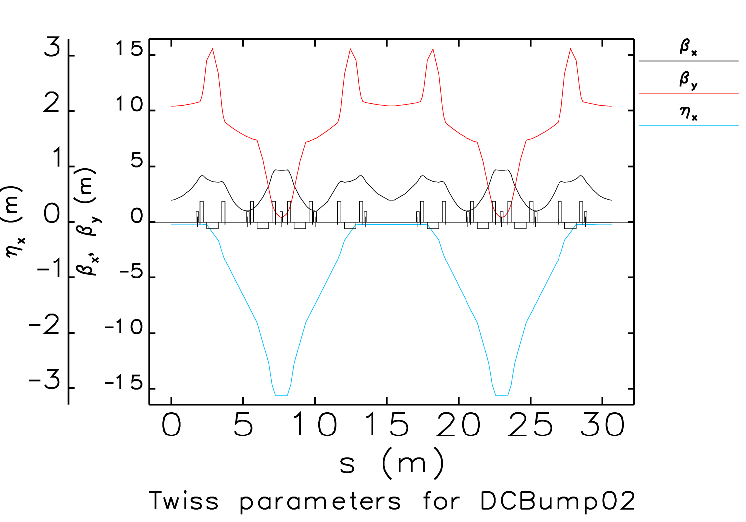
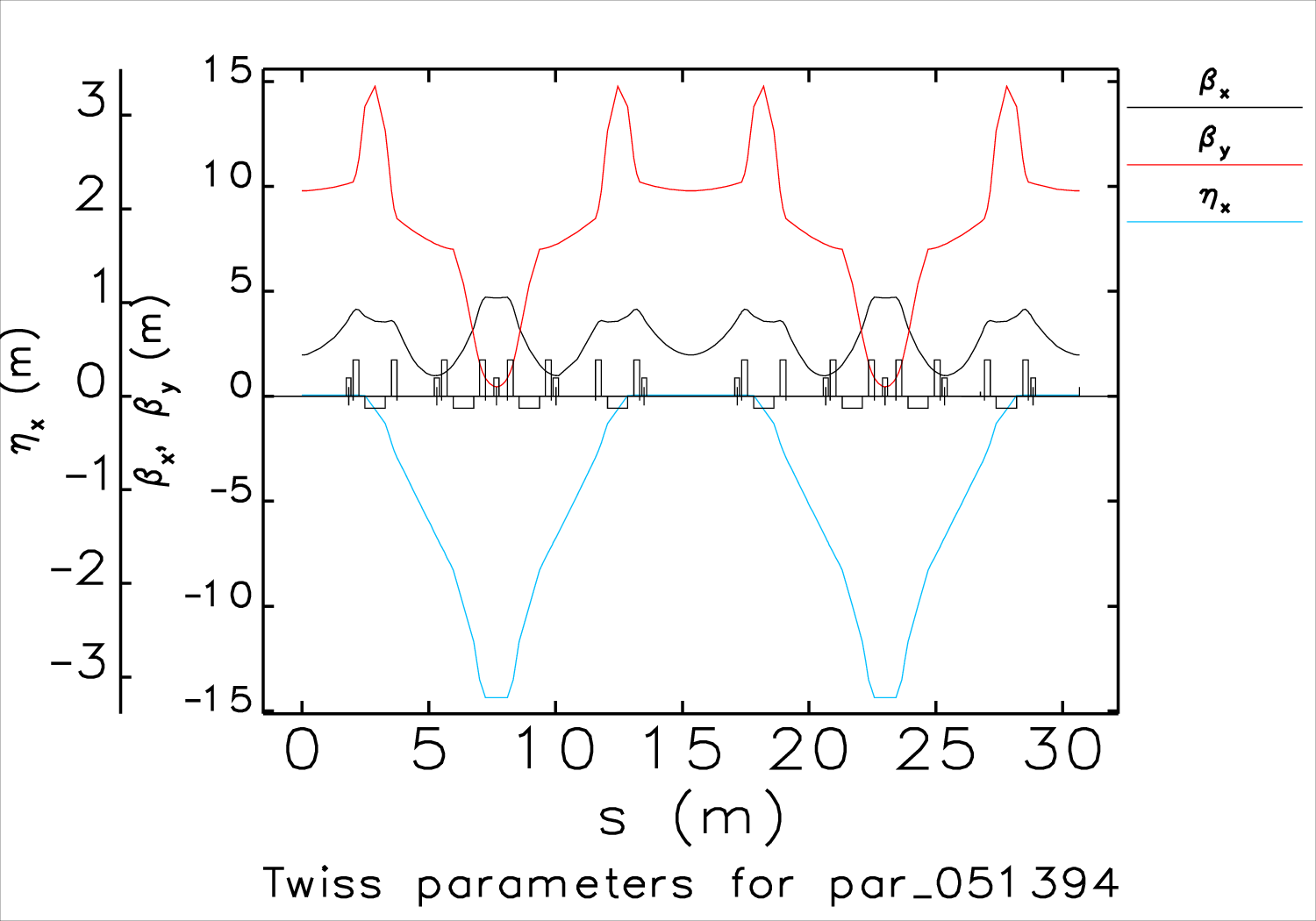
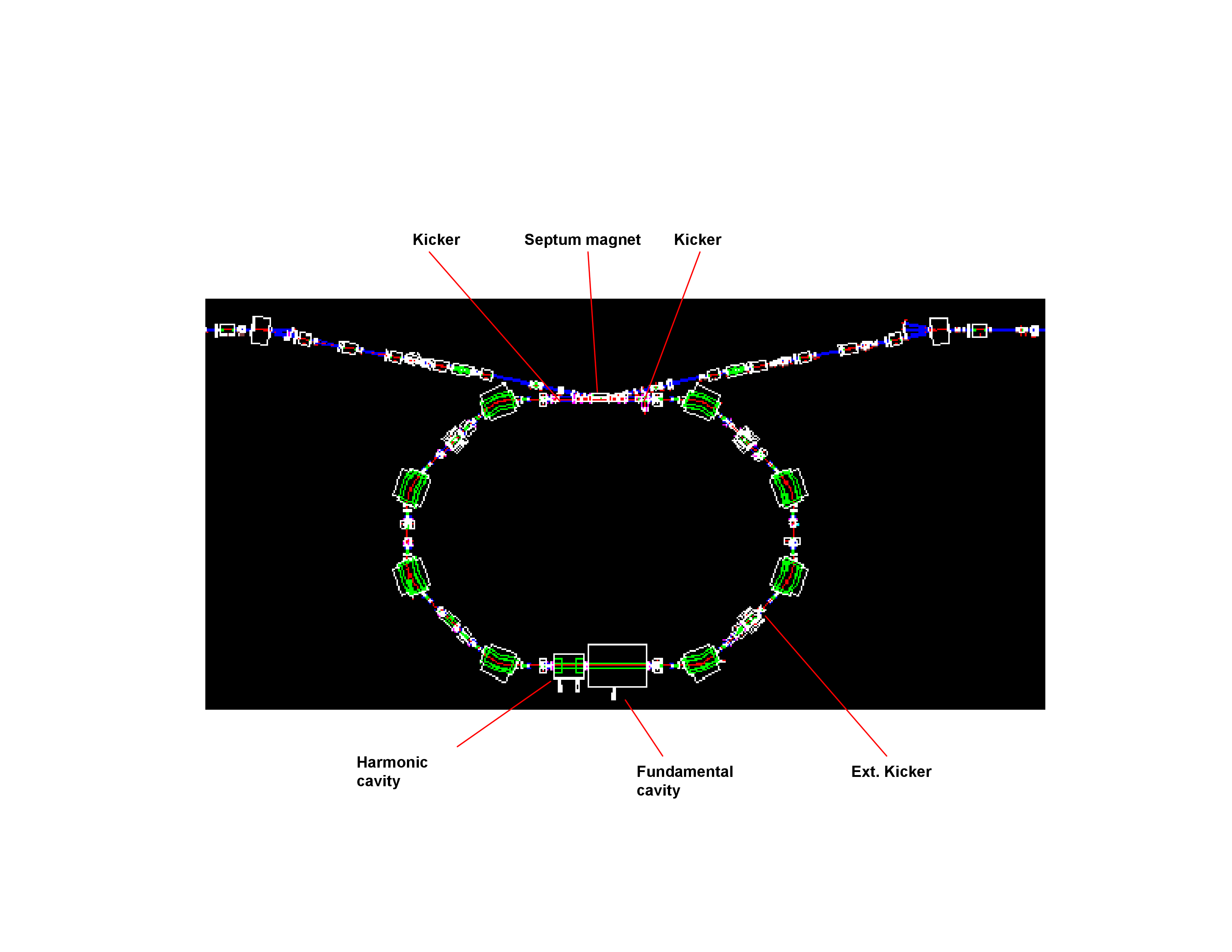
In operations, the PAR beam has a 3-mm DC orbit bump at the septum, which reduces the requirement on kicker pulse amplitudes. Because of the bump, the beam parameters are slightly different than the design lattice. The links listed below give the full lattice definitions in MAD format for the PAR operations and design lattice. The two figure below shows Twiss functions of full PAR lattices. The final figure shows the PAR layout.

Figure 1: Twiss parameters for the operational lattice.

Figure 2: Twiss parameters for the “original design” lattice.

Figure 3: PAR layout