10.91 RFMODE—A simulation of a beam-driven TM monopole mode of an RF cavity.

A simulation of a beam-driven TM monopole mode of an RF cavity.
Parallel capable? : yes
GPU capable? : no
Back-tracking capable? : no


Parameter Name UnitsType Default

Description


RA Ohmdouble0.0

shunt impedance, Ra=Vˆ2  /P


RS Ohmdouble0.0

shunt impedance (Rs=Ra/2)


Q double0.0

cavity Q


FREQ Hz double0.0

Resonant frequency of the cavity mode


CHARGE C double0.0

Deprecated—use CHARGE element)


INITIAL_V V double0.0

initial beam-loading voltage


INITIAL_PHASE RADdouble0.0

initial beam-loading phase


INITIAL_T S double0.0

time at which INITIAL_V and INITIAL_PHASE held


BETA double0.0

normalized load impedance


BIN_SIZE S double0.0

bin size for current histogram


N_BINS long 20

number of bins for current histogram


INTERPOLATE long 0

if non-zero, interpolate voltage within bins


PRELOAD long 0

preload cavity with steady-state field


PRELOAD_CHARGE C double0.0

beam charge used for preloading calculations


PRELOAD_FACTOR double1

multiply preloaded field by this value


PRELOAD_HARMONIC long 0

If detuning from harmonic is greater than half the revolution frequency, automatic determination of the rf harmonic will fail. Give the harmonic explicitly with this parameter.


RIGID_UNTIL_PASS long 0

don’t affect the beam until this pass


DETUNED_UNTIL_PASS long 0

cavity is completely detuned until this pass


RFMODE continued

A simulation of a beam-driven TM monopole mode of an RF cavity.


Parameter Name UnitsType Default

Description


SAMPLE_INTERVAL long 1

passes between samples to RECORD file


FLUSH_INTERVAL long 1000

samples between flushing output to RECORD file


RECORD STRINGNULL

output file for cavity fields


SINGLE_PASS long 0

if nonzero, don’t accumulate field from pass to pass


PASS_INTERVAL long 1

interval in passes at which to apply PASS_INTERVAL times the field (may increase speed)


FREQ_WAVEFORM STRINGNULL

<filename>=<x>+<y> form specification of input file giving frequency/f0 vs time, where f0 is the frequency given with the FREQ parameter


Q_WAVEFORM STRINGNULL

<filename>=<x>+<y> form specification of input file giving qualityFactor/Q0 vs time, where Q0 is the quality factor given the the Q parameter.


RAMP_PASSES long 0

Number of passes over which to linearly ramp up the impedance to full strength.


BINLESS long 0

If nonzero, use algorithm that doesn’t requiring binning. Best for few particles, widely spaced.


RESET_FOR_EACH_STEP long 1

If nonzero, voltage and phase are reset for each simulation step.


LONG_RANGE_ONLY long 0

If nonzero, induced voltage from present turn does not affect bunch. Results are not self-consistent!


RFMODE continued

A simulation of a beam-driven TM monopole mode of an RF cavity.


Parameter Name UnitsType Default

Description


ALLOW_UNBINNED_PARTICLES long 0

If nonzero, will keep running even if some particles fall outside the binning region. Use with caution!


N_CAVITIES long 1

effect is multiplied by this number, simulating N identical cavities


BUNCHED_BEAM_MODE long 1

If 1, then do calculations bunch-by-bunch. If >1, use pseudo bunches.


BUNCH_INTERVAL S double0.0

For pseudo-bunch mode, time between bunches.


DRIVE_FREQUENCY Hz double0.0

drive frequency from generator. If zero, no generator voltage is applied.


V_SETPOINT V double0.0

setpoint for total cavity voltage


PHASE_SETPOINT DEGdouble0.0

setpoint for total cavity phase


UPDATE_INTERVAL long 1

update interval of feedback in units of rf period


READ_OFFSET long 0

Offset in buckets of point at which voltage and phase are read for feedback relative to the first bunch passage. A positive value corresponds to reading before bunch passage.


ADJUSTMENT_START long 0

Pass on which to begin adjustment of the effective voltage setpoint.


ADJUSTMENT_END long 0

Pass on which to stop adjustment of the effective voltage setpoint.


ADJUSTMENT_INTERVAL long 100

Interval in passes between adjustment of the effective voltage setpoint.


RFMODE continued

A simulation of a beam-driven TM monopole mode of an RF cavity.


Parameter Name UnitsType Default

Description


ADJUSTMENT_FRACTION double 0.0

Fraction of voltage setpoint error taken out on each adjustment step


AMPLITUDE_FILTER STRINGNULL

IIR filter specification for amplitude feedback


PHASE_FILTER STRINGNULL

IIR filter specification for phase feedback


IN_PHASE_FILTER STRINGNULL

IIR filter specification for in-phase component feedback


QUADRATURE_FILTER STRINGNULL

IIR filter specification for quadrature component feedback


FEEDBACK_RECORD STRINGNULL

output file for feedback data


MUTE_GENERATOR long -1

If nonnegative, gives the pass on which to mute the generator. This simulates an rf trip.


GENERATOR_FACTOR double 1

Multiplies the generator current by the specified factor.


NOISE_ALPHA_GEN STRINGNULL

<filename>=<x>+<y> specifying alpha(t) for generator noise.


NOISE_PHI_GEN STRINGNULL

<filename>=<x>+<y> specifying dphi(t) for generator noise, in radians.


NOISE_ALPHA_V STRINGNULL

<filename>=<x>+<y> specifying alpha(t) for voltage noise.


NOISE_PHI_V STRINGNULL

<filename>=<x>+<y> specifying dphi(t) for voltage noise, in radians.


NOISE_I_GEN STRINGNULL

<filename>=<x>+<y> specifying ni(t) for in-phase generator noise.


RFMODE continued

A simulation of a beam-driven TM monopole mode of an RF cavity.


Parameter NameUnitsType Default

Description


NOISE_Q_GEN STRINGNULL

<filename>=<x>+<y> specifying nq(t) for quadrature generator noise.


NOISE_I_V STRINGNULL

<filename>=<x>+<y> specifying ei(t) for in-phase voltage noise.


NOISE_Q_V STRINGNULL

<filename>=<x>+<y> specifying eq(t) for quadrature voltage noise.


GROUP string NULL

Optionally used to assign an element to a group, with a user-defined name. Group names will appear in the parameter output file in the column ElementGroup


This element simulates a beam-driven monopole mode cavity using the fundamental theorem of beam loading and phasor rotation. In addition, a generator-driven field may be included using a feedback system [44].

Note on phase conventions: the phase convention for the PHASE_SETPOINT parameter of RFMODE is the same as for the PHASE parameter of RFCA. However, in the output files from RFMODE, i.e., the files requested with the RECORD and FEEDBACK_RECORD parameters, a different convention is used, which differs by -90 degrees from the PHASE_SETPOINT parameter.

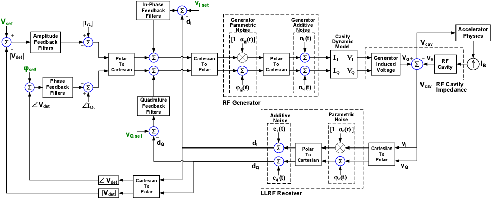
The feedback implementation uses either amplitude and phase feedback or else in-phase and quadrature feedback. Figure 3 shows the model used for the feedback system. More information is available in [44].

Rf feedback is active when a non-zero value is given for DRIVE_FREQUENCY and when either AMPLITUDE_FILTER and PHASE_FILTER or else IN_PHASE_FILTER and QUADRATURE_FILTER are given. These parameters name SDDS files that define filters in the z domain

        m
        ∑ biz-i
H (z) =-i=0-----
        r∑    -i
       i=0aiz
(140)

which translates into the discrete time domain as

         1 ∑r          1 ∑m
y[n] = ----   aiyr-i + ---   bixn- i,
        a0 i=1         a0i=0
(141)

where y[n] is the filter output (e.g., additional generator current) and x[n] is the filter input (e.g., the voltage error signal). The filter files must each contain two columns:

Each file can consist of up to four pages, with each page representing one filter in a parallel filter bank formed from all pages. The output of the four stages is added to obtain the control signal. The number of rows in the page is given by the larger of r or m; in the case of multiple pages, the number of rows in each page is given by the largest r or m from the highest order filter amongst the pages, by simply stuffing the rows of the other pages with zeros, i.e., rows representing orders of z down to z-l where l is the largest r or m of the filter pages.

For example, a digital low-pass filter with DC gain of k can be specified as

y[1] = e-pT y[0]+ k (1 - e-pT)x[0],
(142)

where p is the frequency of the pole and T is the sample interval.

The feedback loop reads the cavity state and acts on the generator at a fixed interval (in buckets) of UPDATE_INTERVAL. The timing of this activity is aligned to the arrival time of the first bunch in the RFMODE element. By default (READ_OFFSET=0), the timing is such that the state is read just before the next arrival of that bunch; in particular, it is 180 degrees ahead of that arrival. If bunches are equally spaced by, say Nb buckets, the UPDATE_INTERVAL parameter should ideally be mNb, where m > 0 is an integer. This ensures that the state is read at a fixed timing relative to the bunches.

The rf feedback feature makes use of the voltage amplitude measured when there is no bunch present. The RECORD file shows the voltage seen by the beam, computed by averaging over the voltage for each particle. These may deviate by values from a few percent to of order ten percent, depending on the loss factor for the cavity and the number of bunchess; this is caused by the fact that the rate at which an intense bunch removes energy from the cavity will typically, albeit briefly, exceed the power from the generator. To reduce the impact of this effect, one may use the ADJUSTMENT_FRACTION, ADJUSTMENT_START, and ADJUSTMENT_INTERVAL parameters to modify the voltage setpoint. If ADJUSTMENT_FRACTION is non-zero, then for every ADJUSTMENT_INTERVALth pass after the ADJUSTMENT_STARTth pass, the voltage setpoint will be adjusted based on a comparison of the bunch-averaged voltage to the user’s setpoint. E.g., if the bunch-averaged voltage is 100 V too low and ADJUSTMENT_FRACTION is 0.1, the voltage setpoint will be raised by 10 V. Users should note that if ADJUSTMENT_FRACTION is too large or ADJUSTMENT_INTERVAL is too small, the system may be unstable.


PIC

Figure 3: Rf feedback model used by the RFMODE element. Courtesy T. Berenc, Argonne National Laboratory.


Normally, the field dumped in the cavity by one particle affects trailing particles in the same turn. However, if one is also using a WAKE or ZLONGIT element to simulate the short-range wake of the cavity, this would be double-counting. In that case, one can use LONG_RANGE_ONLY=1 to suppress the same-turn effects of the RFMODE element.

Two output files are available: the RECORD file includes bunch-by-bunch data on the beam-induced fields and the total cavity fields. The FEEDBACK_RECORD file includes tick-by-tick data from the feedback system simulation; writing this file this can significantly degrade performance.

NB: when BUNCHED_BEAM_MODE is set to a value other than 1, in order to obtain the effect of several bunches while tracking only one bunch, the total charge set with the TOTAL parameter of the CHARGE element should equal the charge in a single bunch, not the entire beam. However, when BUNCHED_BEAM_MODE=1 (allowing an indeterminant number of bunches to be actually present), then TOTAL should be the total for all bunches together.

Explanation of <filename>=<x>+<y> format: Several elements in elegant make use of data from external files to provide input waveforms. The external files are SDDS files, which may have many columns. In order to provide a convenient way to specify both the filename and the columns to use, we frequently employ <filename>=<x>+<y> format for the parameter value. For example, if the parameter value is waveform.sdds=t+A, then it means that columns t and A will be taken from file waveform.sdds. The first column is always the independent variable (e.g., time, position, or frequency), while the second column is the dependent quantity.

RFTM110